2.3 Electric Installation
Static IP Address Setting This subsection describes how to connect the 2N® IP Base main unit to the power supply and LAN and how to connect other elements. Connection of RFID reader modules is contained in section 2.4 Extending Module Connection.
Caution
- The device must be part of the electrical system of the building.
Main Unit Connector Configuration
Description board connectors accessible to users:
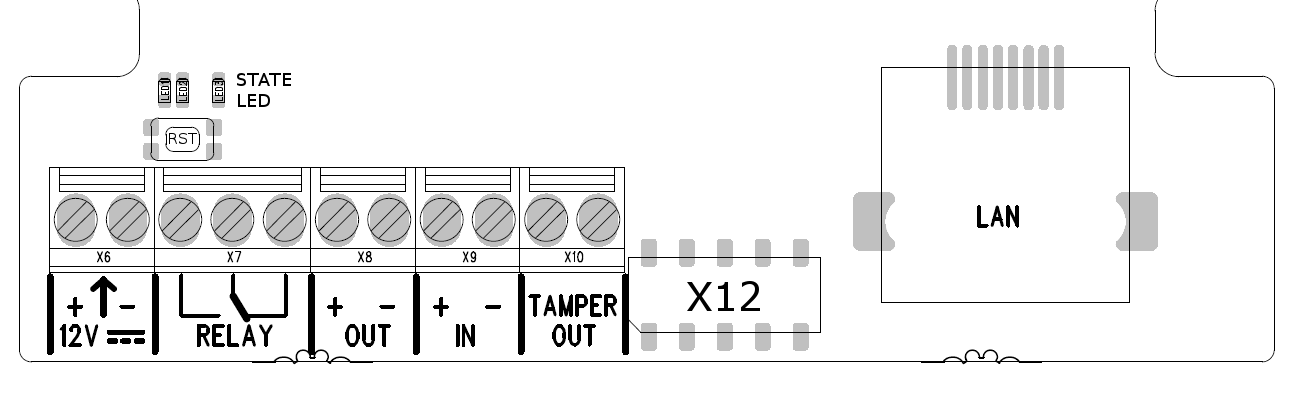 |
| Legend | |
|---|---|
| LAN (PoE) | LAN (PoE according to 802.3af) connector |
| X12 Connector | The connector for RFID Reader modules |
| Tamper | Output of internal security intercom contact |
| IN | Terminals for input in passive / active mode (-30 V to +30 V DC)
|
| OUT | OUT1 active output: 8 up to 12 V DC depending on power supply (PoE: 10 V; adaptor: power supply voltage minus 2 V), max 600 mA |
| RELAY | Terminal 30 V / 1 A AC/DC NO/NC contact. Used for connection of non-critical devices only (lights, e.g.). |
| 12V | External 12 V / 2 A DC power supply terminals |
RESET (RST) | RESET / FACTORY RESET button |
| LED | LED indicators (red – device state / green – eth. link up / yellow – LAN activity) |
- Output wiring diagram for Relay terminals
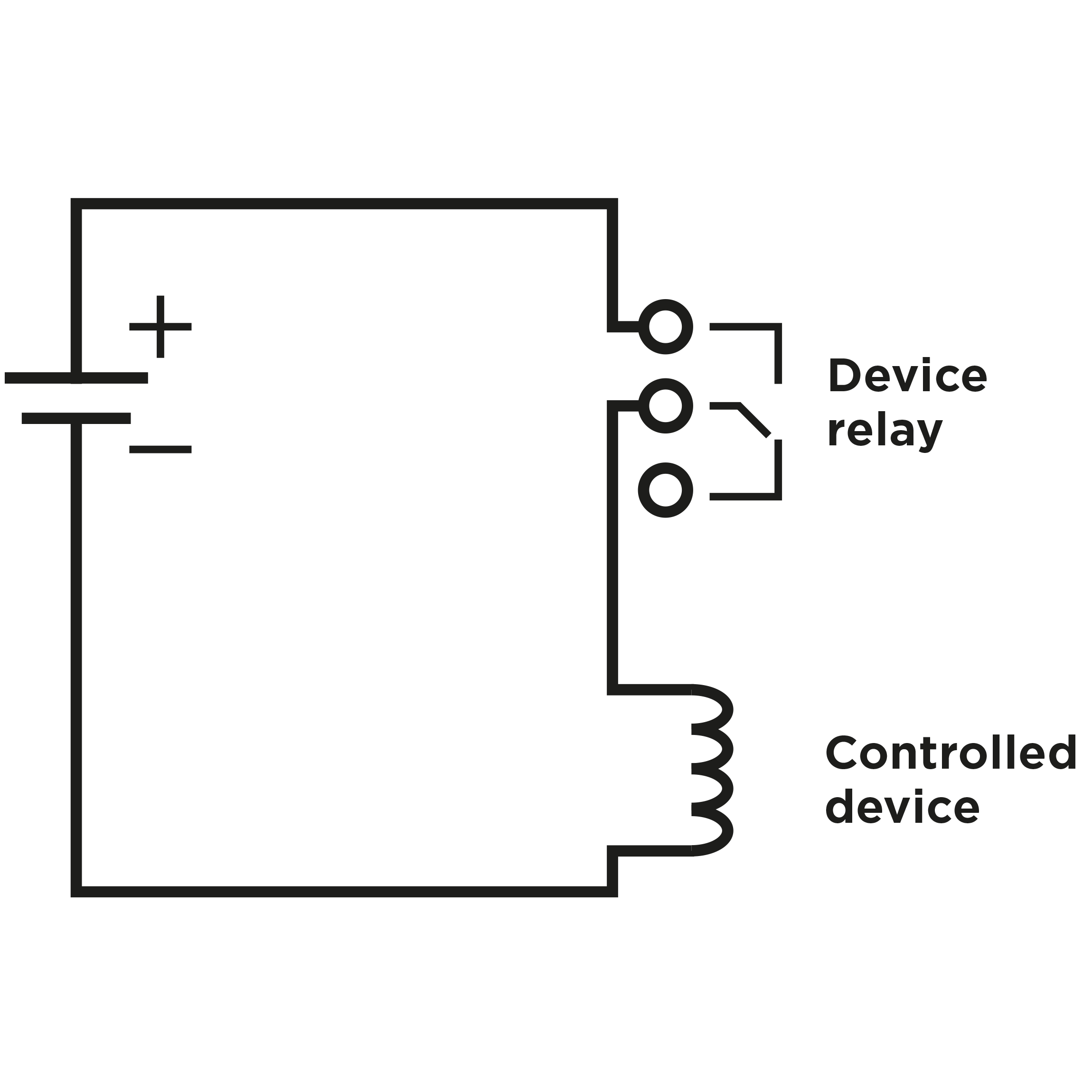 |
Wiring diagram for the controlled device’s electric circuit closing
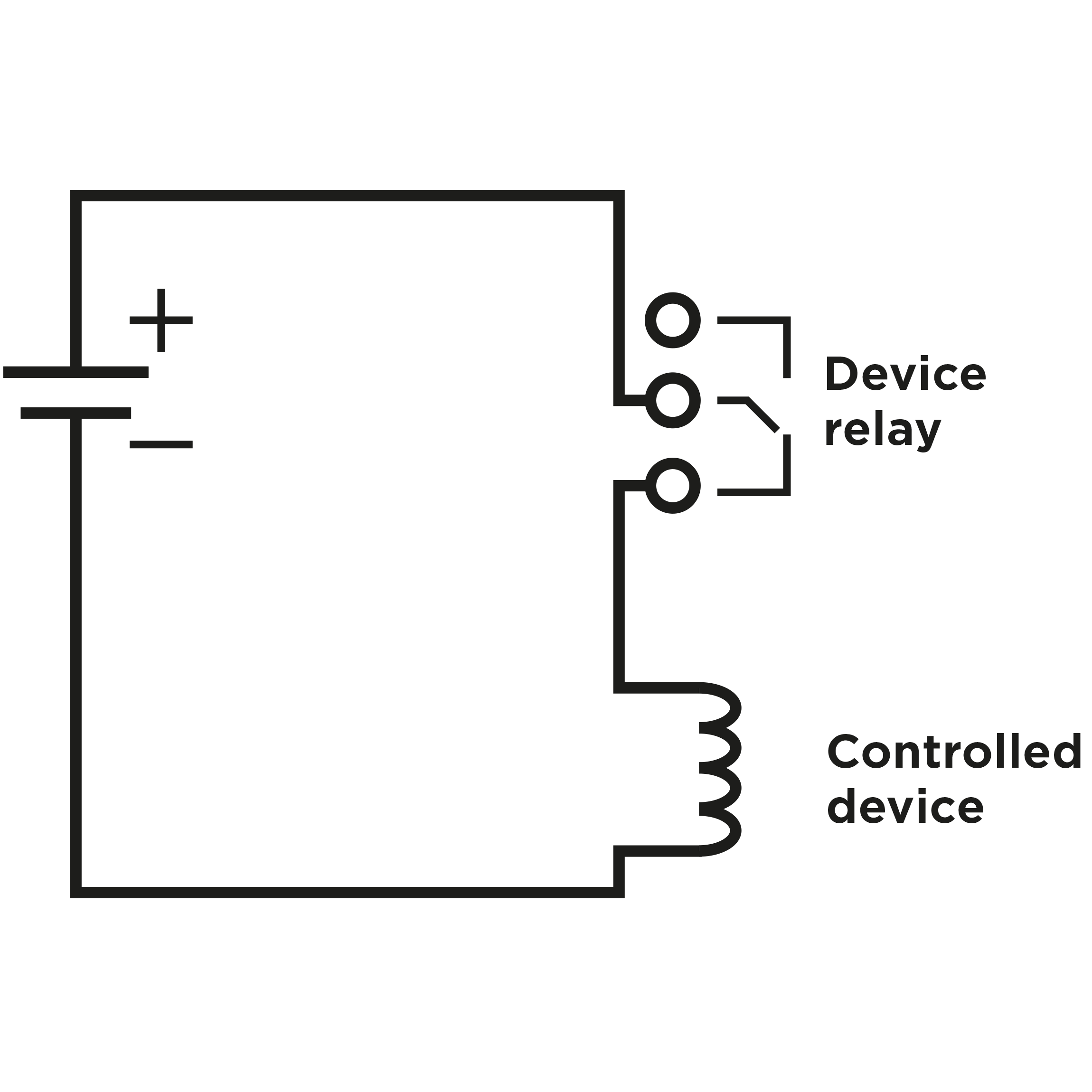 |
Wiring diagram for the controlled device’s electric circuit opening
Tip
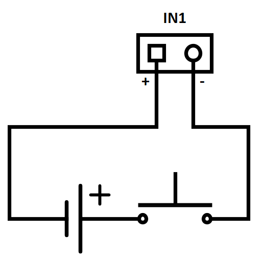
- Wiring Diagram of IN1 connector in active mode
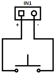 |
- Wiring Diagram of IN1 connector in passive mode
 |
Electric Lock Connection
Connect the electric lock or another electric appliance directly to the device Active input or use a relay to switch the power supply. In the latter case, use an external lock supply. In any case, you are recommended to use low-consumption locks and keep the limits mentioned above.
Warning
When you connect a device containing a coil, such as a relay or an electromagnetic lock, it is necessary to protect the intercom against voltage peak while switching off the induction load. For this way of protection we recommend a diode 1 A / 1000 V (e.g., 1N4007, 1N5407, 1N5408) connected antiparallel to the device.
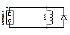 |
Main Unit
Power Supply Connection
2N® IP Base can be powered either from an external 12 V / 2 A DC source or directly from the LAN equipped with PoE 802.3af supporting network elements.
External Power Supply
To make your device work reliably, use a safe 12 V ±15 % voltage supply, Part No. 91341481E (SELV), dimensioned for current consumption according to the required performance, for the main unit supply (2 A, 24 W).
PoE Power Supply
2N® IP Base is compatible with the PoE 802.3af (Class 0–12,95 W) technology and can be fed directly from the LAN via the compatible network elements. If your LAN does not support this technology, insert a PoE injector, Part No. 91378100, between 2N® IP Base and the nearest network element. This power supply provides 2N® IP Base with 12 W for feeding of the main unit.
Combined Power Supply
2N® IP Base can be fed from an external power supply and PoE at the same time.
LAN Connection
2N® IP Base is connected to the Local Area Network (LAN) via the UTP/STP cable (Cat 5e or higher) terminated with an RJ-45 (LAN) connector. As the device is equipped with the Auto-MDIX function, both the straight and crossed cable can be used.
Caution
- We recommend the use of a LAN surge protection.
- We recommend the use of a shielded SSTP Ethernet cable.
Reset Button
Located among the main unit connectors, the Reset button helps you reset the factory default values, restart the device, find the device IP address and switch the static/dynamic mode.
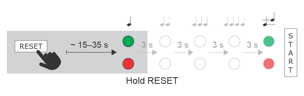
IP Address Finding
Follow the instructions below to identify the current IP address:
- Press and hold the RESET button.
- Wait until the red and green LEDs go on simultaneously on the device and the acoustic signal
 can be heard (approx. 15–35 s).
 - Release the RESET button.
- The device automatically announces the current IP address.
 |
Note
- The delay after pressing RESET till the first light and sound signalling is set to 15–35 s depending on the 2N IP intercom/answering unit model used.
- 18 s is the valid value for 2N® IP Base.
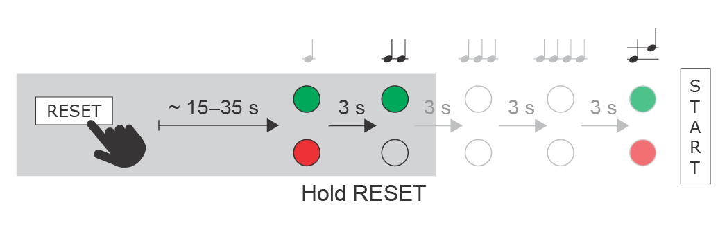
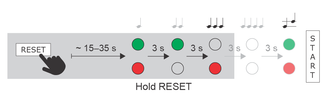
Static IP Address Setting
Follow the instructions below to switch on the Static IP address mode (DHCP OFF):
- Press and hold the RESET button.
- Wait until the red and green LEDs go on simultaneously on the device and the acoustic signal
 can be heard (approx. 15–35 s).
 - Wait until the red LED goes off and the acoustic signal
 can be heard (approx. for another 3 s).
 - Release the RESET button.
The following network parameters will be set after restart:
- IP address: 192.168.1.100
- Network mask: 255.255.255.0
- Default gateway: 192.168.1.1
 |
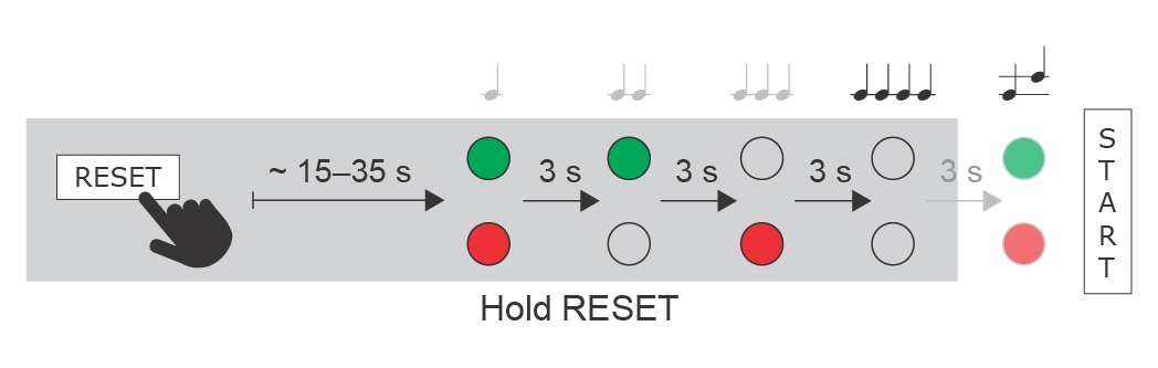
Dynamic IP Address Setting
Follow the instructions below to switch on the Dynamic IP address mode (DCHP ON):
- Press and hold the RESET button.
- Wait until the red and green LEDs go on simultaneously on the device and the acoustic signal can be heard (approx. 15–35 s).
- Wait until the red LED goes off and the acoustic signal can be heard (approx. for another 3 s).
- Wait until the green LED goes off and the red LED goes on again and the acoustic signal
 can be heard (approx. for another 3 s).
 - Release the RESET button.
 |
Factory Reset
Follow the instructions below to reset the factory default values:
- Press and hold the RESET button.
- Wait until the red and green LEDs go on simultaneously and the acoustic signal can be heard (approx. 15–35 s).
- Wait until the red LED goes off and the acoustic signal can be heard (approx. for another 3 s).
- Wait until the green LED goes off and the red LED goes on again and the acoustic signal can be heard (approx. for another 3 s).
- Wait until the red LED goes off and the acoustic signal
 can be heard (approx. for another 3 s).
 - Release the RESET button.
 |
Caution
- In case of resetting the factory default settings on a device with a version of firmware 2.18 or higher it is necessary to reprogram the
2N® Security Relay using the instructions from section 2.4.
Device Restart
Press the RESET button shortly (< 1 s) to restart the system without changing configuration.
Note
- The time interval between the short press of RESET and reconnection after restart is 26 s for 2N® IP Base.