2.3 Electric Installation
This subsection describes how to connect the 2N® IP Audio Kit into your Local Area Network (LAN) and how to connect supply voltage and other electric interfaces.
Warning
- Do not connect any power until the assembly and installation are complete.
Device and PCB Connectors
The figures below show the layout of the 2N® IP Audio Kit and 2N® IP Audio Kit Lite connectors and terminals.
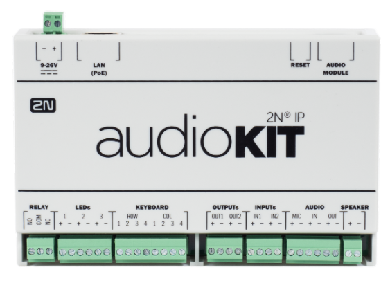 |
Version R394-1
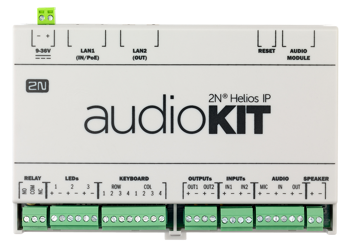 |
Version R345v2
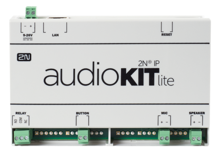 |
Connectors
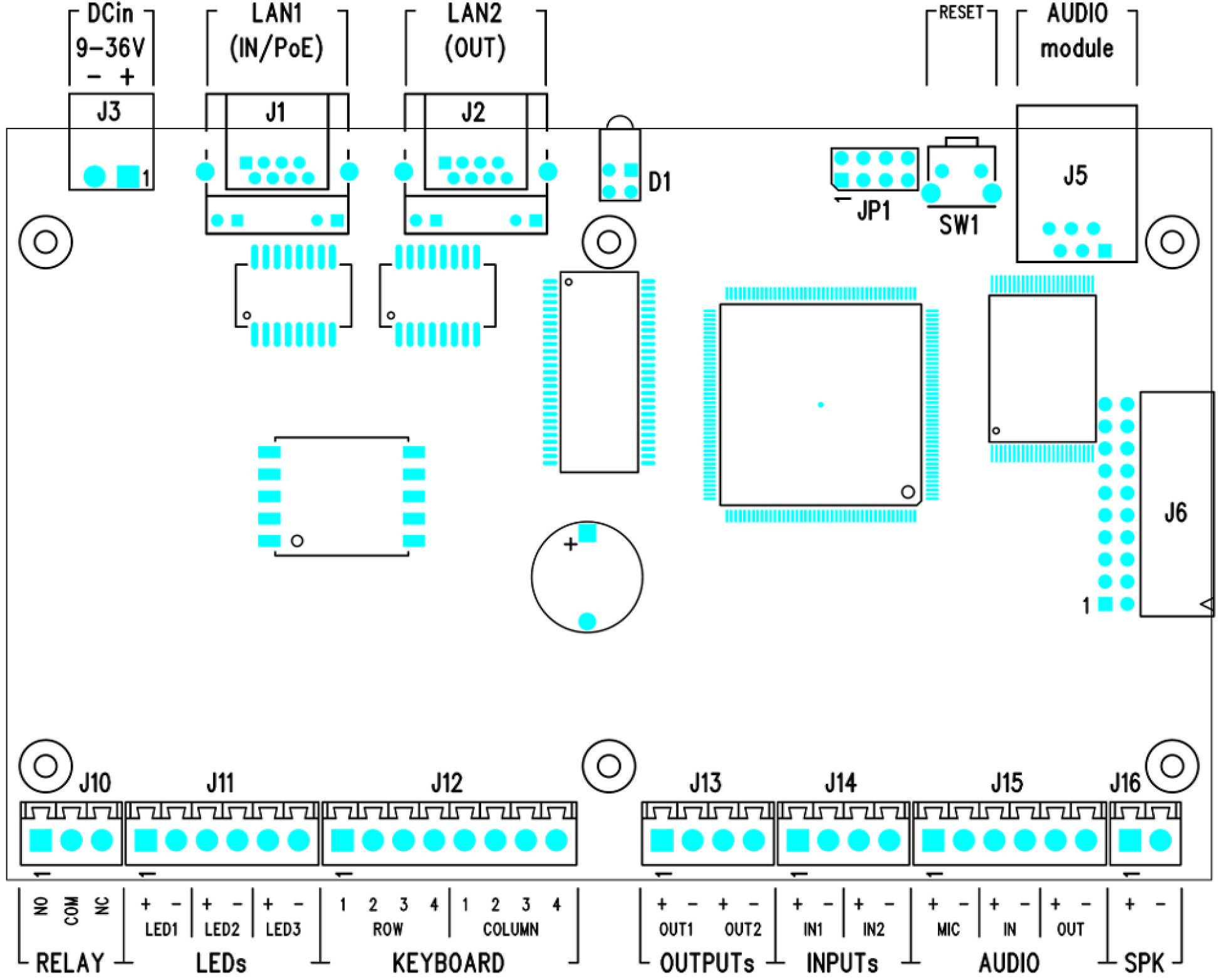 |
PCB Connectors
| Legend to figures | ||
| Group | Terminals | Function |
DC in | Power input 9 to 26 V ± 10 % / 2 A DC, typically 12 V DC | |
LAN1 | LAN connection with PoE function, not available at Lite version | |
LAN2 | LAN connection, available only for R345v2 version, not available at Lite version | |
| LAN | Only at Lite version, LAN connection | |
D1 | Integrated red and green LED indicators, not available at Lite version | |
RESET | RESET multifunction button | |
AUDIO MODULE | Connection of an audio module with microphone, loudspeaker, buttons and LEDs | |
RELAY | NO, COM, NC | Programmable relay switch with an accessible N/O and N/C contact. Used for connection of non-critical devices only (lights, e.g.). |
LEDs | LED1+, LED1− LED2+, LED2− LED3+, LED3− | 3 current outputs for connection of programmable LED indicators; two terminals per LED, not available at Lite version |
KEYBOARD | COL1–4 ROW1–4 | Connection of matrix keypad (4 x 4) or 16 separate buttons, not available at Lite version |
| BUTTON | Only at Lite version, a button is mapped to pins COL1 ROW4. This position is mapped to sign * by default. Refer to the section Connection of Keypad/Buttons. | |
OUTPUTS | OUT1+, OUT1− | 2 programmable active outputs ( supply from PoE: 10 V DC; suply from external source: voltage minus 2 V, max. 11 V DC ) output current: Max. 600 mA, not available at Lite version |
INPUTs | IN1+, IN1− IN2+, IN2− | 2 programmable galvanically isolated inputs, not available at Lite version |
AUDIO | MIC+, MIC− IN+, IN− OUT+, OUT− | Microphone input line input, not available at Lite version line output, not available at Lite version |
SPEAKER | SPK+, SPK− | Power amplifier output for loudspeaker |
Connection to LAN
Connect 2N® IP Audio Kit to the LAN using an RJ-45 terminated UTP/STP cable (of category Cat 5e or higher). As the device is equipped with the Auto-MDIX function, you can use either the straight or crossed cable version.
2N® IP Audio Kit is according to the version equipped with one or two LAN interfaces (LAN1 and LAN2) and an integrated Ethernet switch. You can use only LAN1 interfaces for LAN connection. LAN1 is the only interface provided with PoE.
LAN2 helps connect another LAN device on the installation site. This interface is not equipped with PoE.
Note
- 2N® IP Audio Kit does not allow you to feed another connected device via PoE. The integrated PoE function is intended for the
2N® IP Audio Kit supply only.
Caution
- We recommend the use of a LAN surge protection.
- We recommend the use of a shielded SSTP Ethernet cable.
Connection of External Power Supply
2N® IP Audio Kit can be supplied either from an external 9–26 V / 2 A DC source or directly from the LAN provided with the PoE 802.3af supporting network elements.
External Power Supply
Connect the external 12 V power supply to the DC in terminals. Use safety low-voltage voltage (SELV, 9–26 V) dimensioned for the minimum current consumption of 2 A (Part No. 91341481E, e.g.) to make your device work correctly.
PoE Supply
2N® IP Audio Kit is compatible with the PoE 802.3af technology (Class 0–12.95 W) and can be supplied directly from the LAN via compatible network elements. If your LAN lacks such compatible elements, you can insert a PoE injector, Part No. 91758100E, between your 2N® IP Audio Kit and the nearest network element. Connect your 2N® IP Audio Kit to the LAN via the LAN1 interface to supply it successfully.
Caution
- In case you feed your 2N® IP Audio Kit via PoE or from a limited-power external power supply, monitor the power consumption of the whole system. With regard to the PoE 802.3af capacities and efficiency of the switched-mode power supplies in the device, the maximum possible device input is approximately 12 W. An overload of the PoE source usually results in PoE disconnection and, subsequently,
2N® IP Audio Kit restart. - The 2N® IP Audio Kit consumption at relax (power amplifier inactive, no load switched on LED1–3 and OUT1–2 outputs) is up to 2 W.
- The maximum power amplifier consumption is determined by the current loudspeaker volume level and impedance (up to 10 W for a 4 Ω loudspeaker). The real consumption is typically lower and depends on the characteristics of the signal to be amplified.
- If you intend to connect a considerable load to the OUT1 and OUT2 outputs, make sure that the total input does not exceed the above mentioned limit (12 W for PoE). If the PoE supply fails to provide sufficient power for the specific application, use a more powerful external source to make your device work perfectly.
Connection of LED Indicators
2N® IP Audio Kit is equipped with three independent current LED control outputs (LED1±, LED2± and LED3± terminals). All of them are current outputs (20 mA, up to 12 V). You can connect the LEDs directly to the terminals of these outputs or use LEDs with serial resistors. Mind the polarity while connecting the LEDs to make your device work properly.
The functions of the LED1, LED2 and LED3 outputs are programmable.
Connection of Keypad/Buttons
2N® IP Audio Kit is equipped with an interface for connection of an external matrix keypad or up to 16 separate buttons; see the figure below:
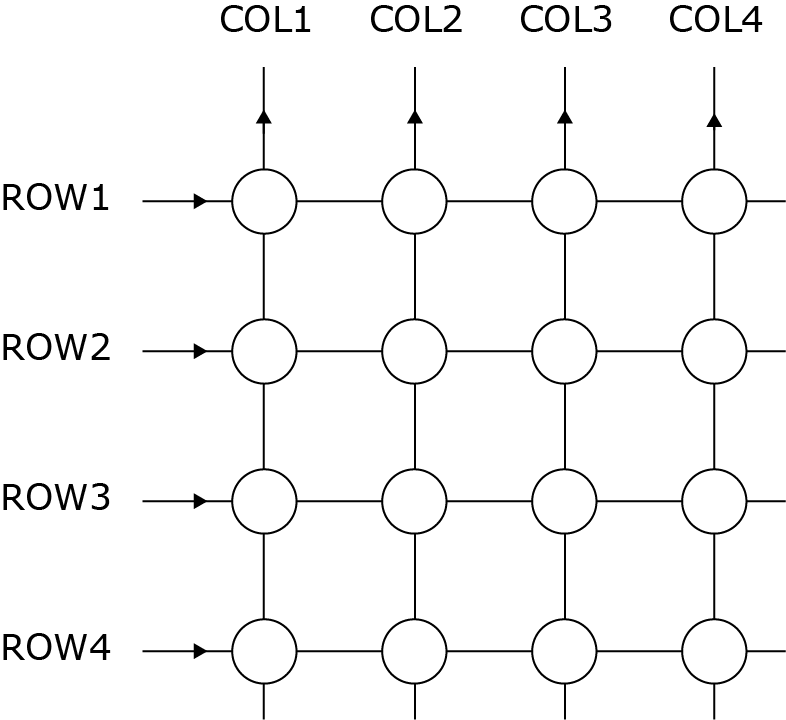 |
The buttons are connected in a 4 × 4 matrix to the ROW1–4 (output) and COL1–4 (inputs) terminals. If you do not make use of all of the 16 buttons, you can leave some of the ROW and COL signals unconnected. If you need one button only, connect it to the ROW1 and COL4 terminals.
The button function is programmable. You can set the numerical keypad buttons to any matrix position (0 to 9, *, #) or configure one of the 16 buttons for dialling a telephone directory position.
Caution
- Errors such as false keystroke detection may occur in installations with strong EMI. Therefore, make sure that the keypad or button cables are carried in a trunk separated from the power cables and are as short as possible (up to 1 m).
- Lite version has a button (BUTTON) connected to the terminals COL1, ROW4. In a default configuration, a keypad button * is configured at this matrix position.
Connection of External Loudspeaker
2N® IP Audio Kit is equipped with an integrated 10 W power amplifier of class D. The amplifier output is available on the SPEAKER+ and SPEAKER- terminals. The maximum power is achievable with a 4 Ω loudspeaker only.
The higher the loudspeaker impedance, the lower the maximum power output; refer to the table below:
Loudspeaker impedance | Maximum power (at +20 dB) |
4 Ω (min) | 10 W |
8 Ω | 5 W |
16 Ω | 2.5 W |
32 Ω | 1.2 W |
64 Ω | 0.6 W |
Caution
- Never connect a loudspeaker with impedance lower than 4 Ω to avoid system damage.
- Never exceed the maximum power output designated for the loudspeaker to avoid loudspeaker destruction. Choose a loudspeaker with proper impedance and maximum power values, or limit the maximum volume level in the device configuration.
Use an external power supply to maximise the power output. Make sure that the maximum Master volume value is +6 dB in the Hardware / Audio menu if you use PoE and 4 Ω speaker.
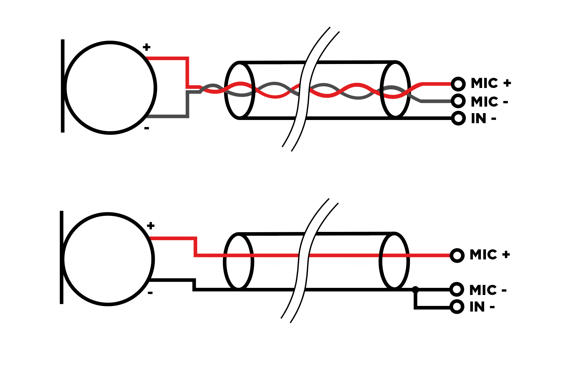
Connection of External Microphone
2N® IP Audio Kit is equipped with an input for connection of an external electret microphone on the MIC+ and MIC- terminals. Shielding of the shielded cable is connected to the IN- terminal.
Caution
- Undesired noise may be heard in the earphone where EMI affects the microphone signal. To avoid this, connect the microphone using a shielded cable of the minimum possible length.
If you use a one-conductor shielded wire, interconnect the MIC− and IN− terminals.
 |
Connection of External Amplifier
2N® IP Audio Kit is equipped with a line output for connection of an external power amplifier on the LINE OUT+ and LINE OUT− terminals.
Connection of External Audio Source
2N® IP Audio Kit is equipped with a line input for connection of an external audio signal source (FM tuner, MP3 player, e.g.) on the LINE IN+ and LINE IN− terminals.
Connection to Relay Output
2N® IP Audio Kit is equipped with one galvanically isolated relay switch with N/O and N/C contacts on the NC, NO and COM terminals. The relay function is programmable.
Tip
- Output wiring diagram for Relay terminals
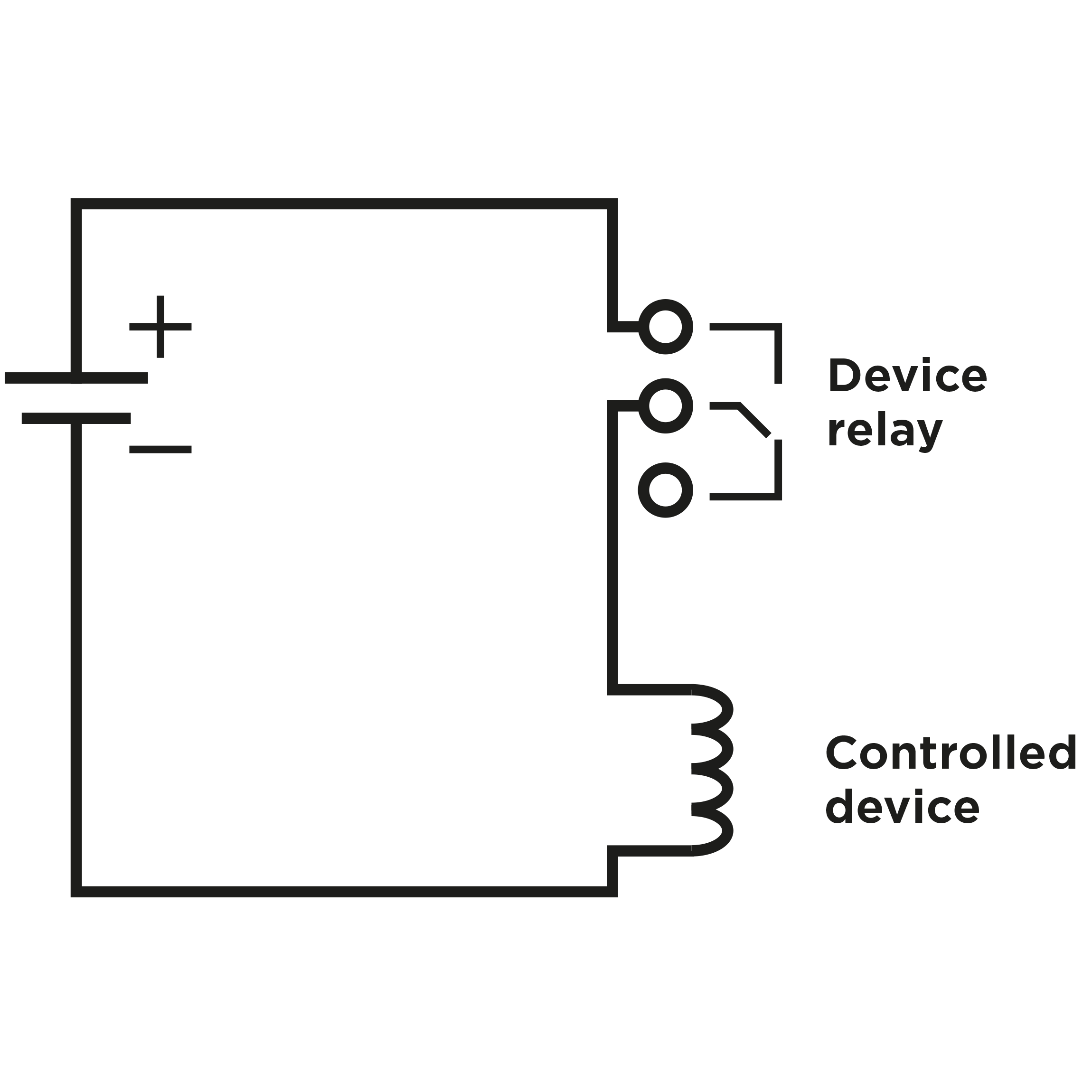 |
Wiring diagram for the controlled device electric circuit closing
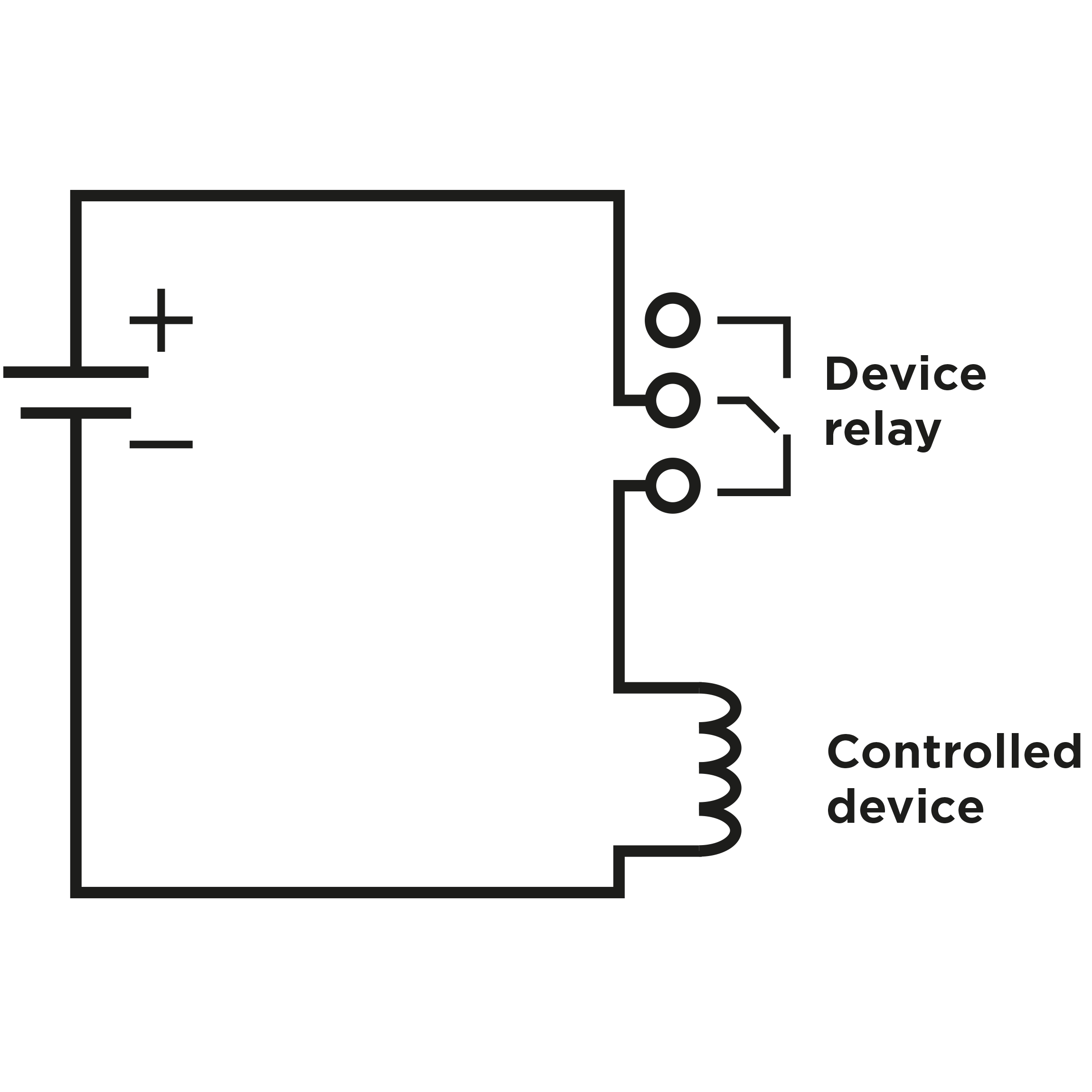 |
Wiring diagram for the controlled device’s electric circuit opening
Warning
- Do not exceed the voltage and current limits for the load connected to the relay contacts as specified in the technical parameters of the device to avoid device damage.
Reset Button
Located among the main unit connectors, the Reset button helps you reset the factory default values, restart the device, find the device IP address and switch the static/dynamic mode.
IP Address Finding
Follow the instructions below to identify the current IP address:
- Press and hold the RESET button.
- Wait until the red and green LEDs go on simultaneously on the device and the acoustic signal
 can be heard (approx. 15–35 s).
 - Release the RESET button.
- The device automatically announces the current IP address.
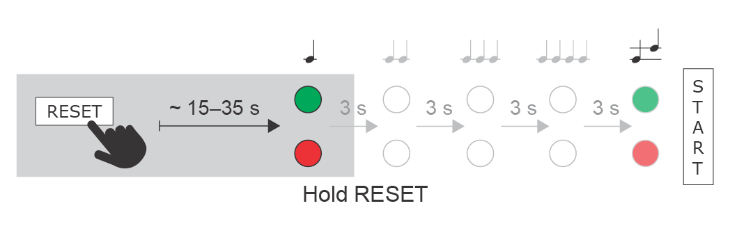 |
Note
- The delay after pressing RESET till the first light and sound signalling is set to 15–35 s depending on the 2N IP intercom/answering unit model used.
- 37 s is the valid value for 2N® IP Audio Kit.
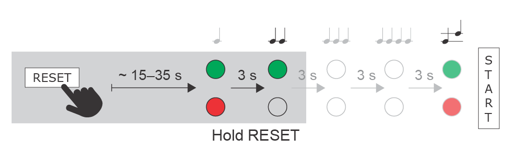
Static IP Address Setting
Follow the instructions below to switch on the Static IP address mode (DHCP OFF):
- Press and hold the RESET button.
- Wait until the red and green LEDs go on simultaneously on the device and the acoustic signal
 can be heard (approx. 15–35 s).
 - Wait until the red LED goes off and the acoustic signal
 can be heard (approx. for another 3 s).
 - Release the RESET button.
The following network parameters will be set after restart:
- IP address: 192.168.1.100
- Network mask: 255.255.255.0
- Default gateway: 192.168.1.1
 |
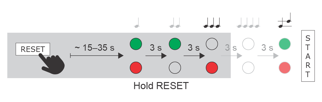
Dynamic IP Address Setting
Follow the instructions below to switch on the Dynamic IP address mode (DCHP ON):
- Press and hold the RESET button.
- Wait until the red and green LEDs go on simultaneously on the device and the acoustic signal can be heard (approx. 15–35 s).
- Wait until the red LED goes off and the acoustic signal can be heard (approx. for another 3 s).
- Wait until the green LED goes off and the red LED goes on again and the acoustic signal
 can be heard (approx. for another 3 s).
 - Release the RESET button.
 |
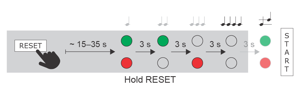
Factory Reset
Follow the instructions below to reset the factory default values:
- Press and hold the RESET button.
- Wait until the red and green LEDs go on simultaneously and the acoustic signal can be heard (approx. 15–35 s).
- Wait until the red LED goes off and the acoustic signal can be heard (approx. for another 3 s).
- Wait until the green LED goes off and the red LED goes on again and the acoustic signal can be heard (approx. for another 3 s).
- Wait until the red LED goes off and the acoustic signal
 can be heard (approx. for another 3 s).
 - Release the RESET button.
 |
Caution
- In case of resetting the factory default settings on a device with a version of firmware 2.18 or higher it is necessary to reprogram the
2N® Security Relay using the instructions from section 2.4.
Device Restart
Press the RESET button shortly (< 1 s) to restart the system without changing configuration.
Note
- The time interval between the short press of RESET and reconnection after restart is 47 s for 2N® IP Audio Kit.
Connection to Digital Outputs
2N® IP Audio Kit is equipped with two active outputs (supply from PoE: 10 V DC; suply from external source: voltage minus 2 V, max. 11 V DC, output current: max 600 mA) on the OUT1± and OUT2± terminals. The outputs are overload and short-circuit resistant. The output function is programmable.
Warning
When you connect a device containing a coil, such as a relay or an electromagnetic lock, it is necessary to protect the intercom against voltage peak while switching off the induction load. For this way of protection we recommend a diode 1 A / 1000 V (e.g., 1N4007, 1N5407, 1N5408) connected antiparallel to the device.
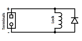 |
Connection to Digital Inputs
2N® IP Audio Kit is equipped with two digital inputs on the IN1± and IN2± terminals. The digital inputs recognise the following two logic levels: log. 0 for voltage under 1.1 V a log. 1 for voltage over 3 V. Keep the voltage polarity to make the function work properly. The function is programmable for either input.