2.3 Electric Installation
This subsection describes how to connect 2N® Analog Uni into your Local Area Network (LAN) and how to connect supply voltage and the electric lock.
PCB Connectors
Description of Connectors:
- LINE – An analogue telephone line with any polarity, or an RJ connector or terminals
- 12V AC, DC – AC/DC backlight or additional amplifier supply (DC must be used for the amplifier)
- tamper N.C. – Open cover signalling contact (N/C)
- GND – Ground (mandatory)
- door N.O. – Electric lock switch (N/O)
- mic. vol. – Microphone level low switch
 |
Compatibility
2N® Analog Uni is designed for conventional, analogue telephone lines and works regardless of polarity and line parameters.(Refer to the Technical Parameters) and uses tone (DTMF) or pulse dialling to be programmed. Normally, it is connected to a PBX line however It can also be connected to an analogue line or the GSM interface providing a wireless installation.
Connection to Telephone Line
Connect 2N® Analog Uni simply using LINE terminals. The advantage is that 2N® Analog Uni requires no power supply because all power is fed from the telephone line – except for the button backlight and electric lock, if connected. Nevertheless, 2N® Analog Uni can work without these circuits too and sends an acoustic signal on having been connected to a line (or after having been disconnected from the line for a defined period of time).
External power Supply and Electric Lock Connection
2N® Analog Uni requires 12 V supply for:
- Name tag backlight – current draw of up to 5 mA, AC or DC
- Electric lock – current draw according to the lock type*)
- Additional amplifier if available – current draw of up to 100 mA, DC only!
*) The electric lock can be fed from the same source as the intercom or another supply.
2N® Analog Uni contains a solid-state switch equipped with V-MOS transistors, which is able to switch both AC and DC regardless of polarity. Make sure that the current and voltage values do not exceed limits (refer to the Technical Data) and that the technical parameters of the lock and power supply are compatible.
Warning
- Never switch 230 or 120 V mains voltage directly!!!
Caution
- If the lock power supply fails and the telephone system carries on working, the intercom is unaware of the failure the switch will be password-activated and the activation is acoustically signalled, but the electric lock will not work because of the lack of power.
- Ground connection is mandatory. If used power supply output is grounded, you can connect GND terminal to it.
Make sure that the power supply is able to supply the required current. Connect the supply and lock as shown in the figure below:
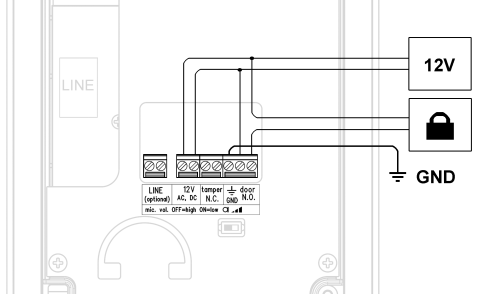 |
Separate Backlight and Electric Lock Supply
Separate power supplies are necessary e.g. where the lock requires voltage higher than 12 V. In this case, an additional power supply (12 V) must be used to illuminate the button backlight – see the figure below:
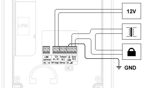 |