2.3 Electrical Installation
Compatibility
2N® Analog Vario is designed for conventional, analogue telephone lines and works regardless of polarity and line parameters.(Refer to the Technical Parameters) and uses tone (DTMF) or pulse dialling to be programmed. Normally, it is connected to a PBX line however It can also be connected to an analogue line or the GSM interface providing a wireless installation.
Connection to Telephone Line
Connect 2N® Analog Vario simply using LINE terminals. The advantage is that 2N® Analog Vario requires no power supply because all power is fed from the telephone line – except for the button backlight and electric lock, if connected. Nevertheless, 2N® Analog Vario can work without these circuits too and sends an acoustic signal on having been connected to a line (or after having been disconnected from the line for a defined period of time).
Printed Circuit Board (PCB) Description
Explanatory notes to the figure:
- Terminal board
- Left button connector
- Display connector (for version 10 only)
- Voice memory
- One-chip Hands-Free telephone
- Switch 2 connector
- Keypad backlight connector
- Connector for non-standard functions
- Microphone connector
- Keypad connector
- Extension unit connector
- Serial number
- Main microprocessor
- Configuration jumper block
- Right connector
- Jumpers
- Camera connector
- Camera setting jumpers
- Loudspeaker connector and panel grounding
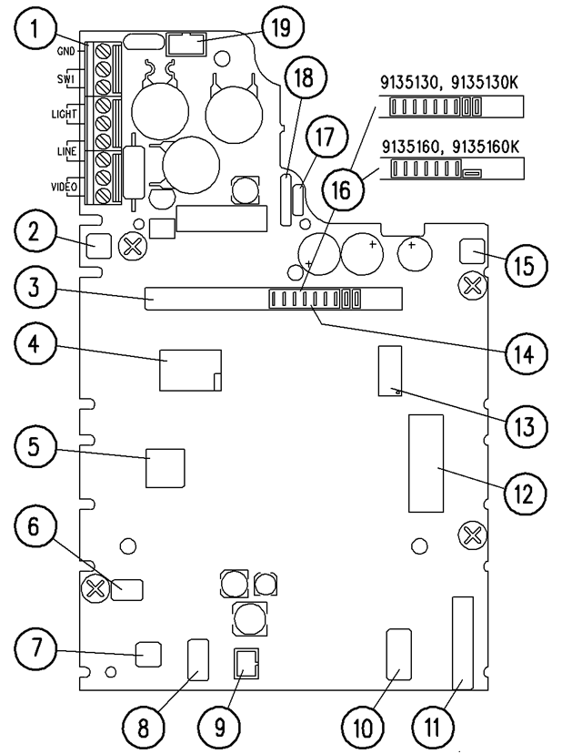 |
PCB Layout, Version 10
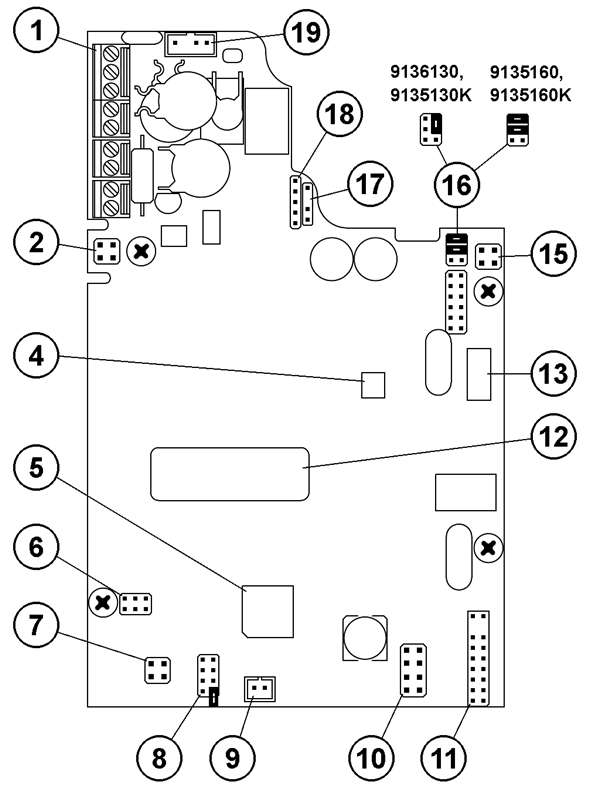 |
PCB Layout, Version 14
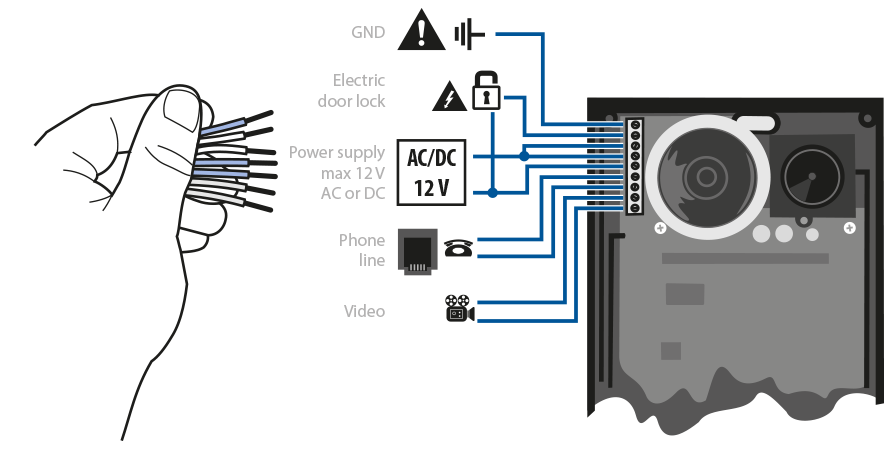
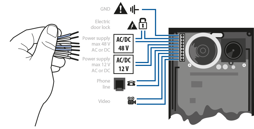
Description of Terminals
- GND – This terminal protects 2N® Analog Vario against static electricity damage.
- SW1 – Switch 1 designed primarily for electric door lock control.
- LIGHT – These two terminals are connected to the 12V power supply with arbitrary polarity. The power supply can feed the electric lock too.
- LINE – These two terminals are connected to the analogue telephone line with any polarity.
- VIDEO – Video signal output – used only if a camera unit is included. The coaxial cable is connected with an internal conductor to +, with shielding to −.
Description of Jumpers
Connector (8)
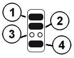 |
- Here connect the current call indicator (LED).
- Write-protection (if the jumper is mounted).
- do not connect
- Microphone sensitivity reduction (mount the jumper for noisy environments).
Camera setting – connector (18): refer to the instructions enclosed to the camera unit.
Parallel Connection
Parallel connection of multiple telephone sets was commonly used in the era in which telephone lines were rare, It carries unnecessary risks to connect the unit in this way. It is in no case recommended to connect 2N® Analog Vario in parallel to another telephone or another 2N® Analog Vario door communicator. It is neither admissible to use equipment that switches one line between two or more sets (intelligent double branch, etc.).
Typical Electric Lock Connection
2N® Analog Vario contains a solid-state switch equipped with V-MOS transistors, which is able to switch both ac and dc regardless of polarity. Make sure that the current and voltage values do not exceed limits (refer to the Technical Data) and that the technical parameters of the lock and power supply are compatible.
 |
Warning
- Never switch 230 or 120 V mains voltage directly!!!
If you do not have an electric lock and want to have one, you should select a 12 V lock, this being the most common type. Connect the lock according to the figure, which shows the button backlight supply too (see later).
Dc-supplied lock: Practically all locks can be dc and ac supplied. The ac supply is more advantageous because the lock buzzes, which is the clearest signalling method however to use a dc supply lock (from batteries, e.g.), you are recommended to equip 2N® Analog Vario with acoustic signalling (continuous tone during the whole switch activation time).
Caution
- If the lock power supply fails and the telephone system carries on working, the keypad-equipped 2N® Analog Vario system is unaware of the failure the switch will be password-activated and the activation is acoustically signalled, but the electric lock will not work because of the lack of power.
Typical Backlight Power Supply
2N® Analog Vario features a high-quality white-LED name plate backlight. This backlight shows low power requirements, long life and even illumination of all name plates. If a standard 12 V electric lock (see above) is connected to 2N® Analog Vario, the backlight can be powered using the lock power supply. Connect the power supply as shown in the figure. Just make sure that the power supply (adapter transformer) is able to supply the required current constantly and that it is cooled properly (do not wrap it in any thermally insulating material, or use ill-ventilating covers, etc.!). The required current depends on the count of buttons and other elements in the set and can be determined for 12 V according to the following formula:
- Basic unit without keypad: 80 mA
- Basic unit with keypad: 200 mA
- 1 one-side extender unit: 80 mA
- 1 two-side extender unit: 100 mA
- Camera: 130 mA
The above mentioned currents are maximum values at 12V.
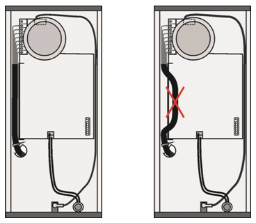
Cable Arrangement inside the Cover
We recommend you to use a UTP cable (8-wire, approx. 5.5 mm output diameter) for 2N® Analog Vario connection. Push the cable into the groove on the left side of the cover. If you combine this cable with another one (e.g. the electric lock 2-wire cable), insert the 2-wire first and then the UTP cable to prevent the 2-wire cable from falling out. You can also fit the cables with common clamp tape.
Warning
- An improper cable arrangement may cause a malfunction of the product. Before closing the cover, check all wires and the cover for perfect closing.
 |
Grounding Terminal Connection – Mandatory
Any person that gets in contact with 2N® Analog Vario may carry an electrostatic charge of several thousands of Volts. Drawing one's finger near to the 2N® Analog Vario metal panel may result in spark discharge. The purpose of the grounding terminal is to protect the product against this discharge. The terminal carries the charge from the panel to the ground directly, not through the 2N® Analog Vario circuits.
Where no grounding cable is available, it is possible to connect the grounding terminal with any of the telephone line terminals*). In some telephone systems one line terminal is directly connected with the ground, the others carry current to the ground through overvoltage protection.
Note
- This connection eliminates direct connection of the line conductor onto the panel because there is a protective element between the panel and the grounding terminal.
Separate Backlight and Electric Lock Supply
Separate power supplies are necessary where the lock requires voltage higher than 12 V. In this case, an additional power supply (12 V) must be used to illuminate the button backlight – see the figure below. Other reasons for such connection are the effort to minimise consumption from the back-up supply (which supplies the lock, not the backlight), or just that two weaker power supplies are available
 |
Connection of Switch 2
A new additional switch, Part No. 9135250E, has been designed for 2N® Analog Vario. It can be mounted into any basic unit, as an added option. To connect it, follow the instructions included in the switch delivery.