2.3 Electric Installation
This subsection describes how to connect 2N® Analog Force/Safety to your PBX and how to connect supply voltage and the electric lock.
Warning
- Make sure that the device is grounded to make the half-duplex system work properly.
PCB Connectors
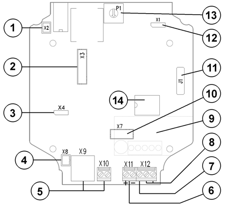 |
2N® Analog Force/Safety Connectors, PCB Version 3
Description of Connectors
| Number | Description |
|---|---|
1 | Loudspeaker connector |
2 | To pushbuttons |
3 | Microphone sensitivity attenuator: high (normal) |
4 | Microphone connector |
5 | Line connection: RJ-12 or screw terminals |
6 | DC power 12 V for power amplifier and for backlight |
7 | Protecting ground |
8 | Switch output |
9 | Additional switch |
10 | To keypad |
11 | Servicing connector |
12 | Power amplifier bypass: Amplifier ON Default = ON |
13 | Power amplifier volume adjustment |
| 14 | DC/DC converter – equipped only on the keypad version |

Compatibility
2N® Analog Force/Safety is designed for conventional, analogue telephone lines and works regardless of polarity and line parameters (Refer to the Technical Parameters) and uses tone (DTMF) dialling to be programmed. Normally, it is connected to a PBX line. However, it can also be connected to CO line or the GSM gateway, providing a wireless connectivity.
Connection to Telephone Line
Connect 2N® Analog Force/Safety simply using LINE terminals – RJ connector or terminal block. The advantage is that 2N® Analog Force/Safety requires no power supply because all power is fed from the telephone line – except for the amplifier, button backlight and electric lock, if connected. Nevertheless, 2N® Analog Force/Safety can work without these circuits too (amplifier is bypassed in this case). 2N® Analog Force/Safety sends an acoustic signal on having been connected to a line (or after having been disconnected from the line for a defined period of time).
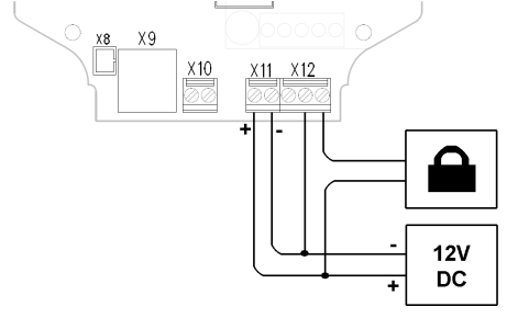
External Power Supply and Electric Lock Connection
2N® Analog Force/Safety require 12 V (DC only!) supply for:
- Built-in audio amplifier – current draw of up to 100 mA,
- Name tag and keypad backlight – current draw of up to 150 mA
- Electric lock – current draw according to the lock type
The electric lock can be fed from the same source as the intercom or another supply.
2N® Analog Force/Safety contains a solid-state switch, which is able to switch both AC and DC regardless of polarity. Make sure that the current and voltage values do not exceed limits (refer to the Technical Data) and that the technical parameters of the lock and power supply are compatible.
Warning
- Never switch 230 or 120 V mains voltage directly!!!
Caution
- If the lock power supply fails and the telephone system carries on working, the intercom is unaware of the failure the switch will be password-activated and the activation is acoustically signalled, but the electric lock will not work because of the lack of power.
- Ground connection is mandatory. If used power supply output is grounded, you can connect GND terminal to it.
Electric Lock Connection
Make sure that the power supply is able to supply the required current. Connect the supply and lock as shown in the figure:
 |
Separate Backlight and Electric Lock Supply
Separate power supplies are necessary e.g. where the lock requires voltage higher than 12 V. In this case, an additional power supply (12V) must be used to illuminate the button backlight - see the figure below.
 |
Grounding
We recommend to ground the intercom in order to improve the static electricity resistance. For proper grounding you need a cable of the minimum cross-section of 4 mm2. Connect the cable to the connector in the bottom part of the intercom. The connector is enclosed to the delivery.
 |
Mounting Completion
- Having connected all the wires, make sure that the bushings, if used, are tightened properly and the RJ-45 connector is inserted in the PCB connector (if used).
- Replace the front cover carefully. Make sure that the wires inside the device leave enough space for the front cover assembly. Tighten the four screws thoroughly with the wrench enclosed (Torx 20) to make the panel fit tightly to the metal chassis.
Caution
- An incorrect mounting may compromise the intercom water tightness. Water leakage may damage the electronic part of the system.
- Stainless steel screws are used for the 2N® Analog Force/Safety assembly. Other screws than stainless steel ones corrode soon and may aesthetically deteriorate the surrounding environment!