2.2 Antenna and Antenna Splitters
2N offers several antenna splitter and antenna models providing the best signal quality on all GSM/UMTS engines. All the systems are designed for all UMTS and GSM networks.
Antenna Splitter
The antenna splitter is designed for decreasing the number of antennas, antenna cables, outdoor antennas and roof mounting space. The antenna splitter is a passive unit suitable for GSM/UMTS gateways. The antenna splitter can be external (2N® StarGate) or internal (2N® BlueTower). Each splitter consists of one or more passive units, each of which has four/two inputs and one output.
Number of inputs | Number of outputs | Input-Output insertion loss | Unit high |
32 | 2 | <15 dB | 2U |
32 | 4 | <11 dB | 2U |
32 | 8 | <8 dB | 2U |
16 | 1 | <15 dB | 1U |
16 | 2 | <11 dB | 1U |
16 | 4 | <8 dB | 1U |
12 | 3 | <8dB | 1U |
Table: Standard External Antenna Splitter Configurations
Number of inputs | Number of outputs | Input-Output insertion loss | Unit high |
4 | 1 | < | 3U |
Table: Internal Antenna Splitters for 2N® BlueTower
Parameters | Value | Note |
Connector type | ||
Input connector | SMA type, female | |
Output antenna connector | N type, female | |
RF parameters | ||
Impedance | 50 Ohm | |
Frequency | 850 – 2100 MHz | |
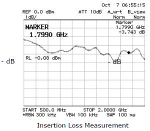
Insertion loss | < 8, 11, 15 dB | According to configuration |
Isolation between two channels | > 20 dB | |
Output overvoltage protection | ||
Device type | Gas surge arrester | |
Protected voltage level | 90 V | |
Peak current | 10 KA | |
Insertion loss | 0.2 dB |
Table: Technical Parameters of Antenna Splitters
Splitter Examples
|
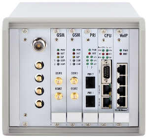
Figure: Internal Antenna Splitter for 2N® BlueTower
|
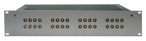
Figure: External Antenna Splitter for 2N® StarGate
|
Directional Antenna
The high-gain directional YAGI antenna is suitable for outdoor and indoor use.
- Type – CPY 9214
- Number of elements – 14
- Frequency – 824 – 896, 1770 – 2100 MHz
- Gain – 9.5 dB / 13 dB
- Cable – RG 58, 10m
- V.S.W.R – < 1.5 : 1
- Connector – N type, female
|
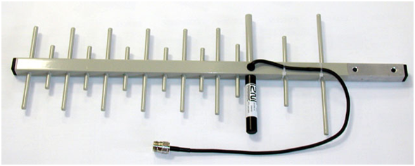
Figure: Directional Antenna
|
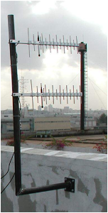
Figure: Example of Correct Installation of Directional Antennas
Warning
- The antenna has to be placed in accordance with the applicable overvoltage protection and grounding safety rules.
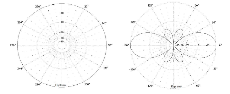
Omni-Directional Antenna
The omni-directional antenna is suitable for outdoor use.
- Type – KA 2290. 9214
- Frequency – 870 – 960, 1710 – 2170 MHz
- Gain – 3 dB
- Polarization – Vertical
- Radiation angle in E-plane – 30°
- Radiation angle in H-plane – omni-directional
- V.S.W.R – < 1.7
- Length – 420 mm
- Weight – 0.6 kg
- Connector – N female
|
|
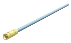
Discreet Antenna
The small omni-directional antenna is designed for indoor use and provides a good GSM/UMTS signal quality.
- Type – Car antenna
- Gain – 2.5 dB
- Cable – Coax cable 174A (5 m)
- Connector – SMA (male)
|
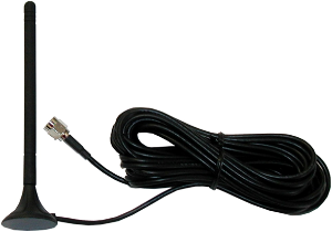
Figure: Discreete antena
Directional Antenna Connection Cable
2N offers you a special low-attenuation cable in variable lengths. The cable terminating connectors are of the N type.
- Type – H1000 PE coax cable
- Impedance – 50Ω
- Operating frequency – 5 – 2150 MHz
- Used connectors – N type (female)
- Cable size – 10.3mm
- Operating temperature – −40°C to +80°C
- Total weight – 120 g/m
- Minimum installation temperature – –5°C
- Minimum static bend radius – 75mm
- Attenuation at 860MHz – 14.1dB / 100m
- Attenuation at 1000MHz – 15.3dB / 100m
- Attenuation at 1750MHz – 21.3dB / 100m
- Attenuation at 2050MHz – 23.4dB / 100m
Installation recommendations
- Preserve polarization,
- Keep minimum distance from lightning conductor
- Keep minimum distance between antennas - half of antenna wave length, that is intended for longest wave length (lowest frequency).
- Consult angle and azimuth used with your provider, respecting location and BTS usage.
- Make sure that incoming performance is not above value, that may cause errors in transmission or even burn out of HF parts.