Basic CPU Board
The basic CPU board carries only the main CPU, which supports all basic features of the gateway (web interface, 2N® SIM Star support, SMS). The advanced features of the enhanced version (SMS2Outlook, SNMP, SMS/Call simulator) are not available.
Board Description
The CPU board contains a processor system controlling the whole system. The board is designed on a 4-layer PCB of the size of 160x100mm. A simple COM1 serial interface, an Ethernet connector (100Base-T) and 5 board status LED indicators are located on the front panel.
|
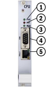
- Indicates board supply; the LED is green if the gateway is powered on and shows no malfunction.
- Indicates board initialisation or malfunction.
- Indicates CDR memory (not shining = empty; flashing 1:1 = 50% full memory; shining = 100% full memory).
- 1st serial interface of the basic CPU.
- 10BaseT Ethernet connection of the basic CPU.
COM1 Serial Interface Parameters
The COM1 interface is used as a local port for temporary connection of a PC (terminal) for installation and servicing purposes and permanent connection of the SMS server (supervision PC). It provides local monitoring, configuration, tracing and firmware upgrade.
- Transmission rate: 57.6 kbps
- Bit format: start, 8bit, stop (no parity)
- Signals: RXD, TXD, RTS, CTS, GND
Configuration Jumpers
The figure below shows the CPU configuration jumper. The JP1 jumper can be connected in one of the following three positions.
- CPU – COM1 communication port is active for communication with the CPU.
- eCPU – COM1 communication port is active for communication with the eCPU.
- DEF – used for CPU default reset.
|
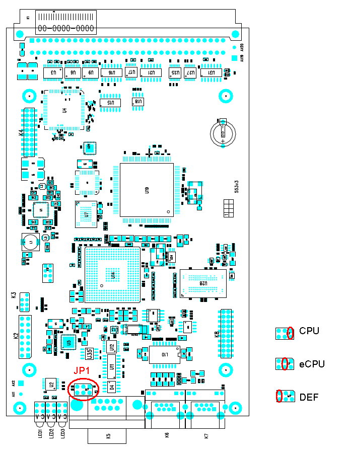
Figure: Configuration Jumpers