3.2 Call Routing Principles
2N® BRI Lite
The gateway is equipped with one BRI ISDN and one VoIP-SIP ports. You can select one of the following incoming call processing modes for each of the ports via the web interface:
- Use LCR table – in this case, calls with be routed as set in the LCR table
- Reject calls – all incoming calls will be rejected
- Route to port – all calls will be routed to the selected port without change
If your BRI gateway is connected to a PBX subscriber line, you can activate DTMF. If you do so, the GSM gateway automatically answers any incoming call from BRI ISDN and offers the caller dialtone for another DTMF dialling. The call will then be routed to the GSM/UMTS modules.
Incoming GSM/UMTS calls can be either DTMF-processed or automatically routed to the ISDN BRI / VoIP-SIP interface according to the active intelligent GSM gateway rules functions (Auto CLIP, CLIP routing). They are routed to the ISDN NT or ISDN TE interface depending on the GSM gateway configuration.
Incoming GSM/UMTS calls can also be rejected and, with the aid of CLIP, used for CallBack.
The LCR algorithm routes outgoing calls on the basis of the call type, current time tariff, day in a week and, if available, free minutes of GSM providers.
2N® BRI Enterprise
The gateway is equipped with two BRI ISDN and one VoIP-SIP ports. You can select one of the following incoming call processing modes for each of the ISDN ports via the web interface
- Use LCR table – in this case, calls with be routed as set in the LCR table
- Reject calls – all incoming calls will be rejected
- Route to port – all calls will be routed to the selected port without change
If your BRI gateway is connected to a PBX subscriber line, you can activate DTMF. If you do so, the GSM gateway automatically answers any incoming call from BRI ISDN and offers the caller dialtone for another DTMF dialling. The call will then be routed to the GSM/UMTS modules.
Incoming GSM/UMTS calls can be either DTMF-processed or automatically routed to the ISDN BRI interface according to the active intelligent GSM gateway rules functions (Auto CLIP, CLIP routing). They are routed to the ISDN NT, or ISDN TE interface depending on the GSM gateway configuration.
Incoming GSM/UMTS calls can also be rejected and, with the aid of CLIP, used for CallBack.
The LCR algorithm routes outgoing calls on the basis of the call type, current time tariff, day in a week and, if necessary, free minutes of GSM providers.
Tip
- 2N® BRI Enterprise / BRI Lite can also route outgoing calls into the GSM/UMTS networks according to the B-channel used. In that case, the GSM/UMTS module is paired with a specific B-channel of the ISDN BRI line.
2N® Mobility Extension
2N® Mobility Extension (ME) is a function that turns your mobile phone into an SIP phone taking advantage of all the PBX functions. To make your 2N® Mobility Extension work efficiently, use the 2N® BRI Lite/Enterprise gateway to assign your mobile phone an account with the same SIP parameters (ID/user/password) that help connect your office SIP phone to the SIP Proxy server. After this account gets registered with the SIP Proxy server via 2N® BRI Lite/Enterprise, your mobile phone will work as 2N® Mobility Extension and make use of the services described below.
Advantages:
- You never miss any important call as you are available at all times.
- You can get information SMS messages on missed calls.
- You can control your company PBX call forwarding services from your mobile phone.
- You can make use of a comfortable DTMF code control.
- You need not make complicated forwarding actions as the function is fully automatic.
- ME can work with any SIP Proxy PBX.
- ME can replace any standard VoIP phone.
- Calls to your mobile phone are free of charge or at a moderate cost4.
- You need not integrate a costly DECT system any longer.
Model Situations
“Follow me” function
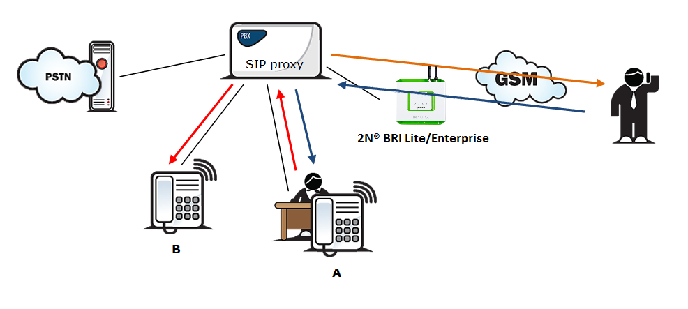
Figure 1: Follow Me Function
Fig. 1 shows routing of calls in the case of absence of a subscriber in the VoIP network. Subscriber A calls subscriber B, for whom the 2N® Mobility Extension function has been permitted with the active “Follow me” function. Subscriber B does not answer the call in the VoIP network and so the call is rerouted to its mobile telephone.
“SMS at no answer” function
In the case of a missed call in the VoIP network, the 2N® Mobility Extension provides sending of an information text announcement. This function is called “SMS at no answer”. Like with call forwarding, it is possible to use the DTMF option to activate and deactivate the service of sending text announcements for missed calls.
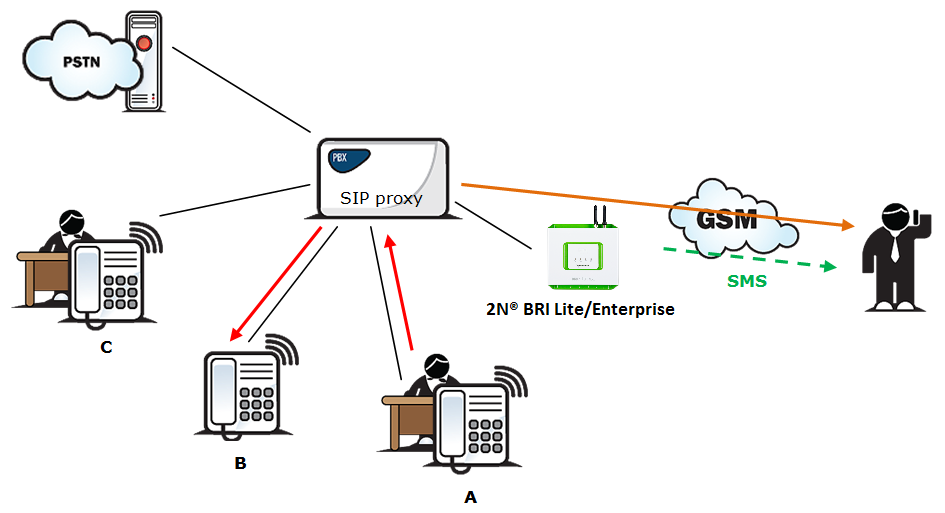
Figure 2: SMS at No Answer Function
Fig. 2 shows sending of information texts if an incoming call is not answered. Subscriber A calls subscriber B, for whom the 2N® Mobility Extension has been permitted with activated “Follow me” and “SMS at no answer” services. Subscriber B does not answer the call in the VoIP network and so the call is rerouted to its mobile telephone. Subscriber B does not answer the mobile phone call and is sent a text announcing that the call from subscriber A has been missed.
"Call forwarding" function
In addition to rerouting calls in the event of absence, the 2N® Mobility Extension allows calls to be forwarded within a VoIP network, which brings the services of the SIP Proxy to a mobile telephone. The description of this function is shown in Fig. 3.
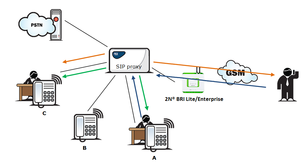
Figure 3: Call Forwarding Function
In Fig. 3 subscriber A is talking to subscriber B, for whom the 2N® Mobility Extension has been permitted. Subscriber A would like to be forwarded to subscriber C. For this reason, subscriber B holds the call with A (7* in the default setting ), dials the number of subscriber C, terminates dialling with the dialling end character (# in the default setting), notifies subscriber C of the call to be forwarded and hangs up to forward the call. If subscriber C does not want to talk to subscriber A, subscriber B terminates the call with C (9# in the default setting) and returns to the call with A.
"Quick call forwarding" function
In Fig. 4 subscriber A is talking to subscriber B, for whom the 2N® Mobility Extension has been permitted. Subscriber A would like to be forwarded to subscriber C. Subscriber B wants to forward the call without having to talk to subscriber C. So subscriber B puts the call with A on hold (7* in the default setting), dials the quick forwarding character (default value #) and dials the telephone number of subscriber C, terminating the dialling with the dialling end character (default value #). Having received the dialling end character, 2N® BRI Lite/Enterprise terminates the call between A and B and attempts to make a call between subscribers A and C. Subscriber A then receives the ring tone.
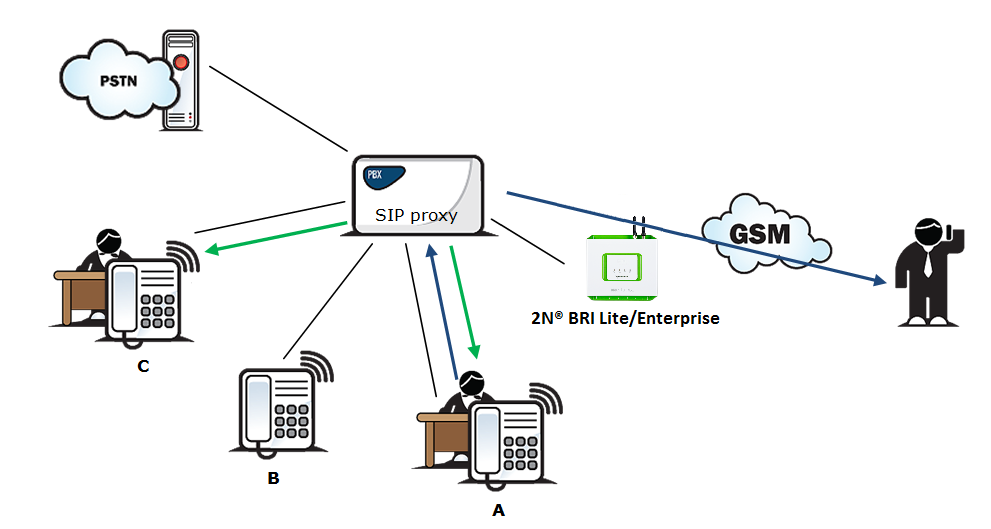
Figure 4: Quick Call Forwarding Function
Correct ME configuration
- Connect the GSM gateway to your PBX/SIP Proxy.
- Check whether the 2N® Mobility Extension licence key has been entered correctly.
- Enter all ME users in the Gateway configuration / Mobility Extension menu.
- Enter the prefix matching the ME user mobile number in the Gateway configuration / prefixes menu.
LCR Table
The LCR (Least Cost Routing) table is the key telephone cost cutting tool. It helps you select call routes according to the called subscriber’s number, daytime and weekdays. By adding bank holidays (with routing rules as on Sundays) to the LCR table you achieve even higher call cost savings.
To make your prefix and LCR routing work properly, enter the prefix of the number to be called to the GSM/UMTS network into the Table of accepted prefixes in the Gateway configuration / Prefixes menu. The number to be called may not exceed the Default count of digits or the higher priority Count of digits setting in the Table of accepted prefixes. The table is searched from top to bottom starting with the first match.
Apply the Table of replaced prefixes to modify the number to be called to the GSM/UMTS network. Every modification is displayed in the "prefix"/"replace with" format (99/+420, e.g.). The Table of replaced prefixes must always contain one record at least or the "/" record if no prefix modification is made. The digits removed from/added to the number in the Table of replaced prefixes are not included in the Count of digits. The table is searched from top to bottom starting with the first match.
GSM network ID is an optional parameter, which is assigned to each LCR record to make the LCR search more convenient. If this parameter is not completed, the list number is only used for identification (1-8).
Poznámka
- Count of digits defines the minimum count of digits to be dialled. Hence, a call is successful if the count of the called number digits is equal to or higher than the value set in the Count of digits.
- The Count of digits does not include the digits removed from/added to the number in the Table of replaced prefixes.
- The Count of digits set in the Table of accepted prefixes has a higher priority than the Default count of digits.
- The Table of replaced prefixes must always contain one record at least or the "/" record if no prefix modification is made.
Make sure that the apriopriate provider's SIM card is inserted in the GSM gateway. Assign the incoming and outgoing groups in the Gateway configuration / GSM groups assignment menu.
For a call setup, the LCR table is searched sequentially from top to bottom. Each LCR table row is assigned a Prefixlist in which the prefix match is searched for. If a match is found, the call will be routed according to the routing group parameters (Groups in the LCR table) as set in the Gateway configuration / GSM outgoing groups table. The call will be connected via the GSM module as assigned to the GSM outgoing groups in the GSM groups assignment table.
If the selected GSM/UMTS module is busy, the call is routed according to the next routing rule included in the Groups and defined by the GSM outgoing groups table. Again, the GSM outgoing group is assigned to a GSM module in the GSM groups assignment table.
The LCR row is checked in this way until a free GSM/UMTS module is found. If no available GSM/UMTS module (GSM outgoing groups) is found, the call is rejected.
Outgoing GSM Call Routing from Internal ISDN
If the GSM/UMTS gateway is connected to a subscriber line of your PBX, you are advised to enable the DISA function to GSM to make your GSM gateway answer every call routed to it by the PBX and wait for further dialling to GSM networks.
The GSM/UMTS gateway routes outgoing calls to GSM as follows:
- The calling subscriber dials a user number.
- If the user dialling is evaluated as Access to GSM gateway, the gateway barred number table is searched through and, if a match is found, the call setup request is rejected.
- With an outgoing call, the gateway waits for further digits to be dialled. This timeout results in a certain delay between the subscriber's dialling and the subsequent dialling by the GSM gateway. Therefore, select the Count of dialled digits for the called destinations while configuring your gateway. Then, the gateway initiates the outgoing call processing algorithm on receiving the last digit.
- The dialling prefix is first checked against the prefixes included in the first row of the LCR table. If no match is found, the following row is used for check and so on.
- In case the prefix and call time comply with the routing rules, the call is routed according to the first LCR rule to the module corresponding to the particular Outgoing GSM group included in the Groups list.
- If the selected GSM module is busy or has a low credit, the preceding step is repeated and the next LCR row is checked.
- In case the selected GSM module is free and has a sufficiently high credit, the GSM gateway starts dialling the GSM number.
- If the calling subscriber number has an unknown prefix or all routes are busy, the GSM gateway rejects the call setup request.
- An outgoing call is not billed until the called party answers the call.
- The GSM network signals the off–hook and the GSM gateway transfers this information to the PBX.
- The gateway is able to generate the AoC tariff pulses during an outgoing call, which, if the GSM gateway is connected to the PBX, allows for call cost logging per user.
Incoming GSM Call Routing
Incoming GSM calls are routed by the algorithm described in the following steps.
Incoming calls are processed according to the Mode parameter in the Incoming GSM calls table. The following options are available:
- Reject/Ignore incoming calls – incoming calls are not routed to extensions. The call setup request can either be rejected or ignored on the GSM side (the calling party hears the check ringing tone).
- Report to PC – information on an incoming call is sent to a PC equipped with the management software. The calling subscriber gets a voice message or the check ringing tone. The management software then completes the call routing procedure.
- CallBack – this function helps establish connection on the account of the SIM card inserted in the gateway. The incoming call is either ignored or rejected. After the calling subscriber hangs up, the GSM gateway sets up connection to the defined extension. When the extension answers, the GSM gateway replays the CallBack message to the extension while establishing connection to the previously calling GSM/UMTS subscriber. After the CallBack message, the GSM gateway interconnects the call. If CallBack with incoming call ignoring is enabled and the calling party fails to hang up within a defined timeout (default=10s), the CallBack function is disabled for this call and the subscriber can go on dialling the extension number. Set the CallBack function in the CLIP routing table.
- If none of the above mentioned options is selected, the AutoCLIP routing table is checked. If the calling number is found, the call is routed to the extension whose number is assigned to the calling number in the table.
- In case the calling number is not included in the AutoCLIP routing table, or the AutoCLIP routing function is disabled, the gateway receives the incoming call and either replays a voice message or transmits the dialtone to the calling subscriber. Then the gateway awaits the count of digits necessary for call setup. Define the minimum and maximum counts of DTMF digits in the Incoming GSM calls menu.
- If the gateway does not receive the minimum count of digits and no other digit comes from the GSM network within the timeout defined in the DTMF dialling delay, the call is rerouted to the extension included in the List of called numbers.
- If call forwarding to extension is inactive, the incoming call is rejected.
DISA Message
With DISA activated and DISA welcome note recorded, the message is played to every incoming call whose CLIP is not included in the AutoCLIP table. After playing, the gateway waits for the first DTMF digit for the time period defined in the Incoming GSM calls – DTMF dial timeout table. Having received the count of digits defined in the Incoming GSM calls – Minimum DTMF digits parameter, the gateway activates connection to the SIP proxy or telephone via the port included in the ISDN parameters table with the DTMF – received number. You can upload the DISA message using the GSM gateway web interface.
Or, you can record the message using your PC as disa.wav and load it into the gateway using the configuration program via the web interface.
DISA Recording via PC and Web Interface
The DISA voice message parameters for PC recording are as listed below: maximum duration of 65s, compression according to ISDN A-law, mono, sampling frequency of 8kHz. Name the file Disa.wav and load it via the Gateway control / Voice messages web interface into the gateway.
DISA voice message parameters:
- Sound format: WAV
- Sampling frequency: 8 kHz
- Channels: 1 mono
- Codec: ISDN A-law