2.2 Brief Installation Guide
Installation Conditions
The following installation conditions have to be met for a proper installation:
- 2N® BRI Enterprise / BRI Lite is to be installed on a site with enough free space.
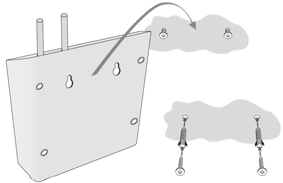
- 2N® BRI Enterprise / BRI Lite is to be mounted on a suitable vertical surface. For this purpose, a hanger is included in the gateway delivery, which is fitted to the wall using dowels and screws and used for gateway hanging.
- It is possible to operate the gateway in another working position too, e.g. on a desk, for a short time for servicing and testing purposes, for example.
- Any excess of the allowed working temperature may not affect the 2N® BRI Enterprise / BRI Lite function immediately but may result in faster ageing and lower reliability. For the allowed working temperature and humidity ranges refer to S. 7.
- 2N® BRI Enterprise / BRI Lite is not designed for high-vibration environments such as means of transport, machine rooms, and similar.
- 2N® BRI Enterprise / BRI Lite is not designed for dusty environments or places exposed to high humidity and temperature changes.
- 2N® BRI Enterprise / BRI Lite may not be exposed to aggressive gases, acid and solvent vapours (during cover cleaning, e.g.).
- 2N® BRI Enterprise / BRI Lite is intended for indoor use. It may not be exposed to rain, flowing water, condensing moisture, fog, and so on.
- 2N® BRI Enterprise / BRI Lite may never be exposed to direct sunshine or placed close to heat sources (radiators).
- A sufficient clearance must be kept over and under 2N® BRI Enterprise / BRI Lite for cabling and air flow to carry off the heat.
- A sufficient GSM/UMTS signal intensity has to be provided for 2N® BRI Enterprise / BRI Lite.
- An adequate capacity of the GSM/UMTS network has to be ensured (no BTS overload). Remember that multiple GSM gateways used in one location may overload the base transceiver station (BTS) you are currently logged in to. This may lead to a permanent or occasional rejection of GSM/UMTS calls!
- No strong electromagnetic radiation is allowed on the 2N® BRI Enterprise / BRI Lite installation site.
- No strong electromagnetic reflections are allowed on the 2N® BRI Enterprise / BRI Lite antenna installation site.
- An inappropriate location of 2N® BRI Enterprise / BRI Lite or its antenna close to television, broadcasting and/or other rf-sensitive sets may impair the function of these sets.
- Being a source of radio frequency emissions, the 2N® BRI Enterprise / BRI Lite antenna should not occur in the close vicinity of the human body. The health hazard is higher than with mobile phones as, generally, gateways shared by multiple users show a very high traffic.
- It is recommended that the power supply adapter should be connected to a network with a UPS back-up and due overvoltage protection.
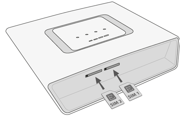
SIM Card Inserting/Removing
Insert the SIM card in the 2N® BRI Enterprise / BRI Lite bottom as shown in the figure. As the SIM slots are of the Push/Pull type, just slide the card in and push it into position. Push the SIM gently to slide it out of the slot.
Caution
- Be sure to set such provider/SIM card services as call forwarding, call barring, preferred networks, SMS centre, etc. in your mobile phone before inserting the SIM card into 2N® BRI Enterprise / BRI Lite.
- If two SIM cards are used, make sure that both the SIM cards have one and the same PIN or PIN code request disable.
- Having inserted the SIM card, restart 2N® BRI Enterprise / BRI Lite to make the SIM card log in.
- Remember to disable the Another call on line service before using the SIM cards!
Antenna Connection
2N® BRI Enterprise / BRI Lite is equipped with a SMA female antenna connector for all the GSM/UMTS modules. The external antenna should always be installed vertically on a site with a good wireless signal.

Warning
- Tighten the antenna connector gently with your hand – never use a wrench!
- Being a source of radio frequency emissions, the 2N® BRI Enterprise / BRI Lite antenna should not be very close to the human body. The health hazard is higher than with mobile phones as, in general, gateways shared by multiple users show a very high traffic.
Note
- The antenna has a sufficient gain for a trouble-free operation under normal conditions. If the signal is poor or you want to place your antenna away from 2N® BRI Enterprise / BRI Lite, you can use an antenna with an SMA-connector terminated cable. The antenna should be mounted vertically.
- Refer to S.7, Technical Parameters, for the antenna parameters.
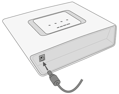
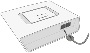
Power Supply Connection
Use only the power supply adapter included in the delivery. Make sure that the electric distribution network voltage is in compliance with the data on the supply adapter plate before plugging the adapter and that the antenna is connected properly. If you connect the power supply without having connected the antenna, the GSM module transmitter may get damaged. Plug the supply adapter into the mains socket and only then connect the adapter connector to the gateway. Refer to the status indicators.
Warning
- Connecting a defective or inappropriate power supply adapter may lead to a temporary or permanent 2N® BRI Enterprise / BRI Lite error!
- Check whether the antenna is connected before plugging the adapter. Feeding the device without antenna connection may result in the GSM module transmitter damage.
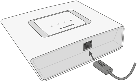
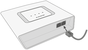
Ethernet Cable Connection
To connect 2N® BRI Enterprise/Lite into the Ethernet network, use a standard straight cable terminated with RJ-45 connectors (included in the package). The GSM gateway supports the 10BaseT and 100BaseT standards, the Ethernet connection status is indicated by the status LED indicators located on the RJ-45 connector (refer to S. 2.1 for details).
Caution
- The Ethernet interface is used for remote supervision and configuration only, i.e. does not contain the VoIP interface.
- With a proper licence, the device provides the VoIP-SIP support.
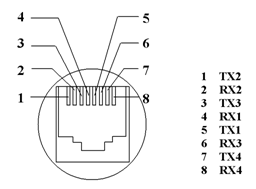
RJ-45 LAN Connector
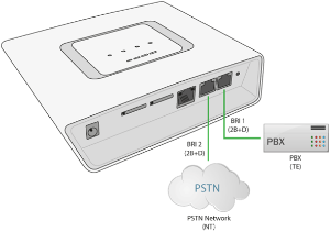
NT and TE Connectors
ISDN devices are connected to the NT/TE connectors depending on the configuration of your telecommunications equipment. They are connected via a 4-wire passive bus with the aid of RJ-45 connectors. Refer to the figure below for the NT/TE connector pin lay-out.
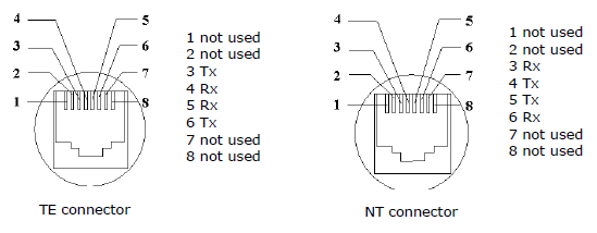
TE connector The figure below shows 2N® BRI Enterprise / BRI Lite connected as network termination (NT) – extension for your ISDN PBX or ISDN phone, i.e. your own equipment.
The figure below shows 2N® BRI Enterprise / BRI Lite connected as terminal equipment (TE) – extension from the ISDN (PSTN), i.e. from your service provider.
An example of the 2N® BRI Enterprise connection in the ISDN mode follows.
Caution
- 2N® BRI Lite is equipped with just one ISDN BRI. Hence, two independent devices cannot be connected at the same time!